Introduction to Inkscape
It’s an everyday need for us researchers to create fluxograms, graphs, schematics or any other graphic way to help the public better understand our results. When it comes to a simple presentation, the default tools may suffice, however, for more complex tasks, we need extra help - that’s when Inkscape comes into play.
Inkscape is a programme dedicated to vector manipulation, which makes it a generic tool to create all sorts of figures, from logos to diagrams. It’s different from GIMP, since the latter is mostly designed to manipulate raster images. If the distinction between vectors and raster images is a little blurry, check out this LibLab tutorial about image formats. Inkscape can be found for download here.
Practical example
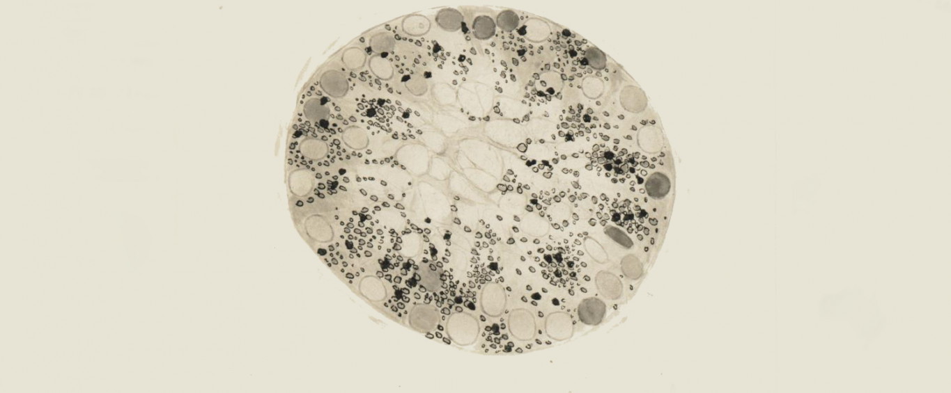
Remember the embryo from the Introduction to GIMP tutorial ? It was this image:

For the purposes of this tutorial, we wish to create a schematic of the embryo image, and to explain its main structures. So… let’s get started with Inkscape !

The Inkscape window should look somewhat like the above. It may vary slightly depending on whether you use a Linux, OS X or Windows version, but the same tools are available in all versions.
Basic shapes
First, let’s create a circle to represent our embryo. To do this, use the “circle” tool, found in the toolbox to the left side of the window. If for some reason you cannot see the toolbox bar, go to View > Show/Hide > Toolbox.

Once the tool is selected, click and drag onto the screen to create your circle. While dragging, keep the Ctrl key pressed to create a circle instead of a ellipse. By holding Shift the circle will be centered on the point you first clicked, instead of this point being the corner of the bounding box.
After creating your object, right click on it and go to “Fill and Stroke”. A small window should open on the right, with 3 tabs:
- “Fill”, which you can use to change the fill color of your object;
- “Stroke paint”, which you can use to choose the color of the object border
- and a last one named “Stroke style”, which enables you to choose the properties of the stroke, such as width, for example.

Keep in mind that although we’re using a circle as example here, the same applies to other shapes that you can find in the toolbox
Aligning objects
Create two circles. Give the first one a light gray, wide border and make the second one a little smaller, with a thinner, dark gray border (see below).

Now let’s center those two circles.
To do this, we can use the “Align and distribute objects” tool that you can find in the top part of the window. If you cannot see it, go to View > Show/Hide > Commands bar. After clicking on the tool, a window should appear on the right side.
With the two circles selected, make sure the “Relative to” option is set to “Last selected” and then click on the options “Center on vertical axis” and “Center on horizontal axis”, represented by the icons with two white objects and a small blue line passing through their center.
The result should be somewhat similar to what you can see below:

NB : Other alignment options are possible, such as with the left or right edges, but for our purposes we want the circles to be aligned and centered.
These two circles represent two different structures of the embryo, the “zona pellucida”, an outer glycoprotein layer that surrounds the early stages of the embryo, and the “trophectoderm”, a layer of cells that in later stages will develop the embryonic annexes. Looking closely at the original image, you may be able to identify both.
The main part of the embryo at this stage is the “inner cell mass”, the dark region you can see on the picture. Let’s model it now.
Creating a custom shape
Generally, when we need a custom shape, the easiest approach is to start from a standard one and modify it. Let’s start with another circle, its size about two thirds of the others’.
For this new circle, you can use the same dark gray as fill color that we have used for the stroke of the previous circle. Do not add a stroke (select the “x” in the “Stroke paint” options).
Now, we can enable the editing of the vectors: select your object and go to “Path > Object to path”. Now select the “Edit path by nodes” tool on the left and click again on your object. You should see something similar to this:

This means that we can now edit each node of the circle individually.
With the “Edit path by nodes” tool selected, drag the top node of the circle down a little. You may hold the Ctrl key to make the movement orthogonal. During the editing, you may want to zoom in on your image, holding the Ctrl key and using the mouse scroll. The result should be similar to the image below:

Scaling and rotating
Now we need to move our object to a position inside the other circles. To move your object as a whole (and avoid editing individual nodes), use the “Select and transform objects” tool (top left on the toolbar).
NB. When selecting the object, you will notice that black arrows appear on the bounding box that surrounds it. You can use these arrows to scale your object and make it fit the inner part of the big circle.
By clicking once again on the object you will enable the rotation tool, and using the curvy arrow on the corner of the bounding box you can rotate your object. The result should resemble what you see below:

If you feel like it, you can edit the nodes again to make the “inner cell mass” fit better with the other objects. When editing the nodes, notice the thin blue lines that cross each one of them. They can be used to control the Bezier curves of the object, as seen below:

Creating text
The “Text” tool, found on the left side of the window, allows us to easily place text on our image.
To do this, click on a blank space and create text objects with the names of the structures. In this case, we will use the terms “zona pellucida”, “trophectoderm” and “inner cell mass”.
To move your text, remember to use the “Select and transform” tool (the black arrow).

Creating lines
We now need to add lines pointing from a structure to the corresponding name.
To do this, use the “Draw bezier curves and straight lines” tool (on the left: the icon is a pencil). Once this tool is selected, you can left-click where you want the line to start, then click on the next node (or nodes if you want). After the last desired node is added, right-click to stop and finish the line. After the line is drawn, you can select it with the “Select and transform” tool and modify its properties – just as we did with the circle object.

Saving and exporting
We now have a nice schematic showing the structures of an embryo which we can easily use in a presentation!
To save your work as a vector file, which can be edited later, just go to “File > Save as”, and select “Inkscape SVG” as the file type.
You may also want to export it as a raster PNG image. To do this, select all your objects and go to “File > Export Bitmap”. In the window that opens, click “browse” to select a place to save your file (and don’t forget the file extension!), then click on export, as seen below:

And that’s it! Your work is now exported and ready to be used!

More tutorials


In this tutorial we explore the GIMP layer system through a practical example.

In this tutorial, let us consider the impact of resolution on printed images.